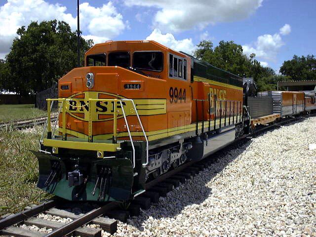
BNSF #9944: Live Steam Scale SD60M
A How-To Project Pictorial
Return to

A How-To Project Pictorial
There are photos, as well as a full length story to read, written originally by Mr Gerry Bowden of Grants Pass, Oregon.
|
The SD-60M Wide Cab Diesel was conceived to fill a need for a locomotive
which:
Numerous locomotive designs in steam and diesel were considered, including
the D&RGW, K-28 & K-36 narrow gauge locomotives. In the end it was felt
that, for ease of operation, a diesel would be chosen and that it would
have to be a design not available on the current market.
Because Cannonball Enterprises Ltd. has an EMD, HTC 3-Axle Truck, we felt
that as large a gas engine as possible should be included. We finally
arrived at the UP SD-60M wide cab diesel.
a. was simple to operate and maintain.
b. would be able to negotiate 5% grades.
c. would haul at least 15 passengers.
The new Briggs & Stratton 18hp "V-2" Vanguard engine should have
sufficient power if used in conjunction with the Eaton Model 11 pump
(20hp) and the new Eaton "M" series Char-Lynn 4HP hydraulic motors which
we found would fit nicely between the truck wheels.
With the combination of 16HP at the wheels, 20HP at the pump, and 18HP at
the engine we should have a good relationship and not overload the pump.
The next item would be the purchase of an "O" gauge model of the UP
SD-60M. Upon doing so we calculated the engine length to be 9'-6" over
the pilots, using the common 1.6"/ft. scale.
The physical outside dimension of the Vanguard engine, however
necessitated an increase of 1" on the width and 1 1/2" on the height for
it to clear the body frame work. The belly fuel tank would not carry
gasoline but instead would be utilized as the hydraulic oil reservoir
tank, which turned out to hold approximately 15 gallons. The combined
weight of the tank and the oil was approximately 250 lbs. This would not
only add weight but would assist in the stabilizing of the diesel.
Because the EMD truck would have operating brakes it was necessary to
install a Cannonball 12-volt air compressor. All the other standard items
were:
a. Electric fuel pump. (rather than the vacuum type supplied with the B&S
engine.)
The hydraulic pump used is the Eaton Model #11, which I have found over
the years to be an excellent unit. The mounting of the pump to the
Vanguard engine uses the same basic principle as Railroad Supply
Corporation with slight modifications to suit the larger B&S engine. I
had valuable assistance in the hydraulic design from Mr. Kirk Jensen of
TEX-A-DRAULICS in Houston Texas, which supplied the pump and motors. The
hoses were Aero Quip type FC-300-6, rated at 3,000 psi on the high
pressure side and 300 psi from the charge pump on low pressure side.
Using Aero Quip type reusable fittings I was able to custom fit all the
hydraulic hoses. Incorporated in the hydraulic system was a 3,000 psi
bypass valve so that the engine could be moved without the engine
running. This valve was installed between the hydraulic inlet and outlet
of the pump.
b. Electric horns. The standard type I have used on all my engines are
the Delco Remy A-C-D-F tones, which are very close to the prototype sound.
These are very durable; one engine I built 10 years ago still has the
original horns.
c. A bell which was modified from an 8" diameter fire alarm bell.
d. A 10 micro hydraulic oil filter.
e. An 90 amp alternator, ( which will be discussed later)
f. A 6-gallon fuel tank with level indicator.
g. A hydraulic oil cooler.
h. Three 4"x4"x1" muffin fans on the rear of the tunnel and mounted over
the hydraulic oil cooler. Also a 7" diameter, five bladed fan with a
heat resistant motor was mounted in the area of the dynamic brake fan.
i. The electrical control gauges, I will discuss later.
The motors used were the Char-Lynn "M" series, 1.92 cu.in. displacement,
face mounted motors. Two motors were mounted on each set of trucks with
the motor pivoting off the axle. Each motor had a torque compensatory set
of springs. Each motor drives its own axle via a chain pivoting off on
one side. The other side had another sprocket driving the center axle.
Consequently all the axles were driven and if one started to slip it would
be taken up by the other one. The installation of the motors required a
slight modification of the truck frame. Torrington needle bearings were
used for the motor pivot frames as were the journal boxes of the EMD truck
due to the weight of the finished engine.
The main engine frame was constructed of 3 sections of square tubing and
rectangular steel tubing in what I call a triangular section. I have
found that this type of construction is extremely strong. As a test of
this theory the hydraulic oil tank was attached to the frame and blocks
were installed under each pilot beam. A dial indicator was set up at the
center of the frame and the tank filled with 15 gallons of water. The
frame deflected .018th of an inch.
The frame was constructed out of tubing, as stated. Three types were used,
1"x3"x .080 wall, 1"x11/2"x .080 wall and 1 1/4"x1 1/4"x .180 wall. The
bolster plates were made from 1/2"x 6" plates. The pilot plates were made
from 3/16" CRS plate. The whole assembly was wired welded. I had a 6
foot welding table fabricated for some of my larger commercial engines and
this worked perfectly for this engine. I had to avoid putting too much
heat in one spot, which can twist and bend a frame very quickly. This was
the basic frame, other items such as lugs and brackets were added later as
I decided where the other components were going to go. The trucks were
attached to the frame via a 3" diameter x 3/8" boss and a 1/2" diameter
kingpin. The Vanguard engine was mounted to the upper face of the bolster
plate.
The hydraulic belly tank was constructed of 16 gauge steel sheet metal
sides, 1/4" plate ends and 10 gauge bottom. The 1/4" plate ends were used
so that drain plugs and oil temperature sensors probes could be threaded
in. The 10 gauge bottom panel, was used so that in the event of a
complete engine truck derailment, the bottom of the tank could take the
weight without damage. Also added to the forward and rear end of the tank
was a half round steel bar to stop the tank from digging into the rail in
the event of a derailment. As on the prototype an oil level glass was
constructed for a visual level indicator. The oil fill was constructed
out of 1 1/2" diameter steel tubing with a breather cap. The top section
of the tank had a 1" drop section installed. This served two purposes:
a. Eight mounting angles could be welded to the tank and used for bolting
to the frame.
b. To allow the high pressure hydraulic hoses to pass through from each
set of motors and pumps without interference with the other equipment
above.
c. To allow the high pressure by-pass valve to be mounted inline with the
hoses. This valve had an extension rod protruding through the frame with
an indicator showing open and closed position, plus a special key to
operate it.
Attaching the hoses to the pump and motor can be a frustrating problem.
The hoses had to clear obstacles to avoid wear and at the same time be
allowed to flex and move with the trucks. This is where a good catalog
like Aero Quip comes in handy because it is advisable to have formed 90
degree bends rather than sharp ones. When it came time to check the
hydraulic system I removed the motor to axle chains to see if my motor
rotation was correct. I only had to change one set of motor hoses. (Big
sigh of relief.)
The electrical system of the engine was left to a good friend of mine
Jerry Osteumeyer, who over the years has wired all my private and
commercial diesel engines. He still amazes me in that; he doesn't need
schematic diagrams. Whether the engines were 3/4 ton or 5 1/2 ton, they
have always worked the first time. We did find that with all the
electrical gauges, blowers, pumps, horns and bell the engine electrical
rectifier was not enough. Briggs & Stratton put out an addition to the
basic engine in the form of a stub shaft through the front grill. This
required the removal of the recoil starter pull cord which we did not need
as the engine has an electric starter. So with the stub shaft we added a
V belt pulleys and a 90 amp alternator; that took care of the electrical
problem.
Unique on this engine were the operating gauges (where to put them?)
Being hard of hearing, the owner needed them in order to check the
operation of the engine. All told there were 6 gauges to be placed in a
proper location. They could not go in the control box as this would be
too big to handle. Then a "Flash!!!" why not install them at the rear of
the tunnel behind two doors? So now an electrical switch on the control
box operates an electro-pneumatic valve which controls two double acting
air cylinders. The rear portion of the tunnel opens and there are the
gauges. Throwing the switch the other way closes them. This way you set
your engine tach and check that the other gauges are correct, close the
door and off you go. The gauges are engine tachometer, fuel level,
hydraulic temperature, amp meter, engine hour meter, and air pressure.
With practice you can guess pretty accurately the RPM of the engine
without looking at the tach.
The gas tank was made of 16 gauge steel and holds 6 gallons of gas. A
standard automotive type float gauge controls the fuel level. The heat
exchanger is again an automotive type used for additional oil cooling.
Added on top of the exchanger, that is mounted 1" above the fuel tank, are
the three 4"x4" muffin fans mounted approximately 1" above the exchanger.
I have found that this cooling system works very well. In heavy hauling
tests with the ambient temperature in the 90's the oil temp has never run
above 110-115 degrees F.
The electrical horns were mounted on a frame work, which straddled and
elevated them above the engine frame. The Cannonball air compressor
system was mounted on its own base plate and again elevated above the
frame. The reason for raising these items was to give as much room as
possible for the hydraulic hoses.
The exhaust system was constructed out of 3/4" ips black iron pipe with a
2 bolt flange connecting this to the cylinder heads. The pipes were
constructed out of 45 degree elbows, nipples and straight sections. They
were joined together with a special "Y" block of steel to form a single
outlet. This then went into a muffler purchased from B&S. Because the
muffler had a round outlet a rectangular box section was made and
protruded through the shell to look like the prototype. The whole exhaust
system was then shielded on the bottom and sides by a two piece aluminum
box section which is removable.
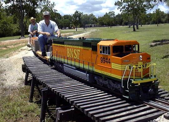
The riding control car was a standard flat car with an imitation wood load
so that the engineer has his feet on the deck while sitting on the load.
The imitation wood load is actually a hinged toolbox and is also the
mounting for the control box. The control box is a 10"x10"x3" fabricated
steel box with a removable top. Two lever control arms for the engine
throttle and the hydraulic directional control were pivoted with a
compression spring to give drag so that they will hold in any position at
which they are set. The remainder of the control box is taken up with
electrical switches for the following:
a. Lights,(headlights, marker lights, ditch lights, flashers.)
The key operated starter switch was mounted on the rear side and fuse
holders are on the left side. This switch has three positions: off,
accessories, and engine start. On accessories all electric components are
actuated; lights, fans, blowers, air compressor, and fuel pump etc. But
on engine start these are cut out so that full battery power is applied to
the engine starter and returned when the key is released. Each switch was
identified by dry transfer letters on the lid, and covered by a 1/8"
plastic sheet for protection. The control box was attached to the dummy
wood load with a special bracket which inclined the box toward the
engineer. The engine throttle and the hydraulic directional controls were
a little bit of a problem in that the throttle linkage was on the left
side and the hydraulic linkage was on the right side, but the connection
on the control box required that they both had to be on the right side.
This was accomplished by a series of cables and linkage terminating at two
levers protruding through the rear pilot. Bowden cables (no relation)
were used from these levers to the control box levers. The inner core of
the cable was .073 diameter stainless steel wire. For safety a solid
1/2"x1 1/4" wide solid steel draw bar was used between the engine and
riding car instead of a coupler.
b. Electrical horn.
c. Electrical bell
d. Electro-pneumatic door opener
e. Parking brakes,(air operated)
f. Vacuum brake switch for passenger cars.
The engine minus the bodywork was loaded on my 10' flat bed trailer for
its first test run at our Medford Oregon track. Special holding brackets
were designed to lock the engine to a 2x6x12' wood stud track framework
which stops the engine from shunting backwards and forwards, up and down
as well as rocking. Also a piece of 3/4" plywood was slipped under the
belly tank to stop the center of the engine from bouncing. Fortunately
little had to be done to the engine other than filling the fuel tank. The
Medford track is in excellent condition so after some slow speed runs were
done we decided to try a high speed run to see how stable the engine was.
A level section was measured and tested with no problems. We estimated we
were moving @ 19mph. On a regular public run day we decided to test the
hauling capacity. Part of our track has a 1 1/2 % grade. Our first load
was 48 passengers. Our second load was 55 passengers. Our final load
was 59 passengers and by then we had run out of cars. After that the
engine was brought back to my shop for a complete inspection and no
adjustments were required other than increasing the drag on one of the
control levers.
The next major project was the body shell. At one time we were
contemplating making it out of fiberglass. But because this engine was
going to be one of a kind, the plug, female model, and finish shell would
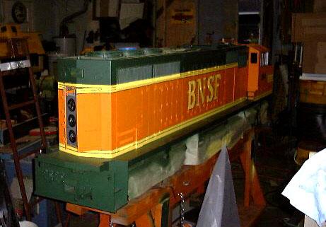
be too expensive. So we used all sheet aluminum. The tunnel was the
first item and what I called the base body was made from 6061-T6 1/8"
thick sheet with a 3/4"x 3/4" x 1/8" alum. angle framework flush riveting
them together. All the top details were made of aluminum bolted to the
base body. The three rear fans were machined from a 1/2" thick plate to
the shape of a angle and the grill frame work was made from 3/32" brass
rods soldered together with silver solder and 50/50 solder. Two of the
four rectangular access doors on top were hinged upward to give access to
the fuel filling cap and the air and electrical disconnect required when
removing the tunnel shell. All the side doors were dummy made from 1/32"
alum. and bonded to the base with an adhesive sealant called UE-6000. A
test of this adhesive was made on two pieces of aluminum sheets and I
destroyed both pieces trying to pry them apart. The hinges and latches
were purchased from RRSC and recessed into the door panels and again
bonded. All the side grills were scratch built from brass angles and
brass perforated sheet formed with a die to a concertina shape as per the
prototype.
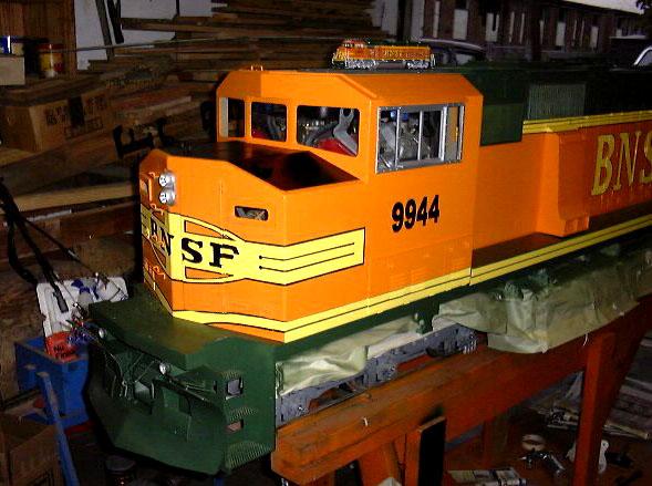
The final project was the cab. Again this was made of 1/8" alum. as the
base. However, the roof and nose had very pronounced radiuses. A neat
trick I found was to clamp a piece of plywood approximately 5' wide bye
the required length in the milling machine vice and "C" clamp the piece of
alum. to it. If, for example, you want a fairly sharp radius bend you
mill a slot 1/8" diameter and approximately 2/3 of the way through the
sheet then bend it on the edge of the bench. It you want a fairly large
radius you mill a slot 1/4" wide and only 1/2 way through the sheet. It
works and you get a straight bend in heavy material. This saves running
to your local sheet metal company. Also you can re-adjust the angle by
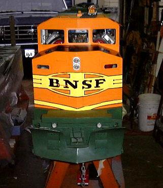
hand if it does not match up exactly. The crew door in the nose was made
to open as this gave access to the electrical disconnect for all the
lighting in the cab section.
All the windows in the cab were left open to allow for air flow over the
Vanguard engine heads. Both the tunnel and cab were then very lightly
sand blasted and painted to match the color scheme of the "O" gauge model.
A final heating test run was conducted at the Medford track with the body
on to see that all the system worked OK. Due to the fact I had built a
Dash8-40CW frame, belly tank and trucks for another customer in Texas I
rented an 18ft van to deliver both at the same time. I have found over
the years that a track made of 2x6 lumber works quite well in transporting
medium weight locomotives. Because the van had an alum. floor and sides I
was not able to tie the engines down properly. By laying 4 or 5 2x6's on
the floor from side to side then screwing down 2x6's on top to make the
track the engines were tied down to them. This worked great even on
several trips to Chicago, Texas, and Los Angeles. Upon arriving at David
Hannah's track in Chappell Hill, Texas near Houston, we found the van to
be too high for the unloading ramp. But with a front loader, a small
ditch was dug to lower the truck rear end, and after that unloading was
easy.
After taking the SD-60M and Dash8-40CW chassis up to the main depot, we
decided to form up a train to see what would happen on the return trip up
the 5% grades. It is advisable when forming a train up, and in particular
when you are going down grade, to form the heavy cars up front and the
light cars to the rear. We had a mid train derailment that would have
made SP proud of us.
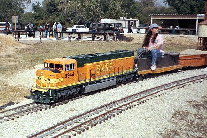
However, after getting everything back in order we continued around and
back up the grade as if it wasn't there. For the train load we had 60
freight cars and 4 passengers cars. In the fall of 1995 the new diesel
returned to Oregon to run at the Southern Oregon Live Steamers track and
at Train Mountain in Chiloquin Oregon. While at Train Mountain, Quentin
Breen was interested in seeing what the diesel would pull on his track, so
he suggested we add 17 propane cars to the four passenger cars already on
the train. Each propane car weighs approximately 400 lb. So with the
weight of the passenger car and the six people riding in the cars and the
additional weight of the loaded propane cars, the SD-60M diesel was
probably pulling close to 5 tons. This was accomplished on a grade of 2%
for over a mile of track, and the diesel never miss a beat. The SD-60M
proved to be a solid running diesel and a well-built hauler.
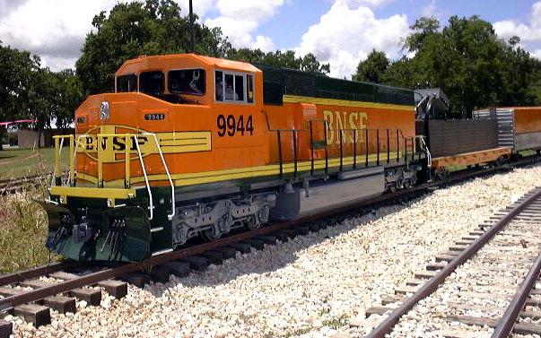
In the fall of 1997 the SD-60M was moved to Zube Park, home of the Houston
Area Live Steamers located in Hockley Texas, after the Browning Plantation
was sold. In the beginning of 1999 the diesel was repainted in the BNSF
Premium Heritage II scheme, and renumbered 9944.