
|

|

|
|
|
|
|
|
|
| Go Back to QStation |
|
Cabless U-boats were first purchased from General Electric by the Burlington Northern in June through August, 1982. The first group of 53 units, numbered 4000-4052 was designated as model B30-7A. They weigh 135 tons each, have a 83:20 gear ratio, 3200 gallon fuel tanks, dynamic brakes, GE type FB-2 trucks, and are 61'-2" long. These new locomotives were soon found on the mainline freights between Northtown, MN and Seattle, WA. The second group of B30-7A's, numbered 4053-4119, began to arrive on the BN in August, 1983. Built to he same specifications, this second group had a new design dynamic brake housing on top of the long hood with a large cooling fan inside. This design was created to save fuel by driving the cooling fan with motor generated electrical current. The motor runs at a variable speed related to the engine speed and cooling needs. Like the first group of B30's this second group was also quickly put into use on the old Northern Pacific main line through Helena and Missoula, MT as well as the old Great Northern "high line" through Havre, Glacier, and Whitefish, Montana. On recent vacations I have photographed these cabless U-boats in various "lash-ups" on both Mullan and Marias Passes in Montana.
Since the dynamic brake housing is distinctive on the second version of this engine, I decided to create a model of it with the dynamic brake box. Because these "B" units are always trailing, and I really don't need the model horsepower, I modeled this engine as a non-powered unit. Athearn's U-33B body shell is close enough to the B30-7A that a reasonable kitbash job is possible. The rear section of the Athearn body shell under the radiators is wider than the rest of the body, as is the prototype. The wide part of the B30-7A prototype extends forward to include the four short doors in front of the radiator section. So this six foot section of the Athearn shell needs to be widened to the same width as the rear part of the body. I used a combination of #11 and #17 knife blades and a rotary saw blade in a Dremel Moto-Tool to cut out the two sections of the body shell with the four short doors. I made the two vertical cuts first, one on each side, using the rotary saw blade. Great care is needed to keep one's fingers out of the way when using this saw. These cuts were made up through the roof just enough to get completely through the plastic. As much of the roof section as possible was left intact. The rotary saw was also used to cut along the walkway, and also down through the roof. A #17 blade was inserted into the saw cuts and used to connect the cuts so that these sections could be removed. The cut out sections, and the body shell, were sanded smooth using a finger nail emery board and a flat mill file. The next operation on the shell was to cut out the roof section and make the dynamic brake fan box. This box is about six feet long from front to back, and is located over the first tall doors behind the cab location. I scribed guide lines lightly six feet apart across the roof, then cut through the roof and down the sides almost to the tops of the doors, using a rotary saw. The saw cuts were sanded smooth as before. I cut out the air intake box section behind the cab of a scrap GP35 body shell, and sanded it to fit into the cutout in the U33B body. The air intake grills on each side of the body just behind the cab were sanded off. The entire low nose section was removed, using a jeweler's saw, and the shell was sanded smooth. To make the high short hood I used an acrylic casting made from a rubber mold of the rear end of a U30B body shell. However, the rear end of a U30B shell could be cut off and used just as well. Making molds is only worth the effort and expense when several of an item are needed. I used the roof section from the fan box cut out to make the top of the high short hood. The sides of this short hood were made of .040" sheet styrene. The roof of the cab was cut out and fitted to place; the sides of the cab were replaced with sheet styrene, and the walkways were filled in with sheet styrene. You may notice that the air intake grills under the radiators are different on the model, but I elected to leave them alone, but some modelers may want to change this. Once all of the body shell pieces were fitted and sanded smooth they were cemented in place with Testor's liquid styrene cement. Tube type cement was was added in places where small gaps needed to be filled in. Thin styrene strips were also used on the inside of the shellto reinforce some of the joint. Any small cuts and imperfections were also filled in with the tube cement and sanded smooth. The cast on drop steps, step boards and grab irons were sliced off with a sharp #17 hobby blade and sanded smooth where necessary.
There are not a lot of additional detail parts to be added to one of these "B" units. Missing on these engines are an antenna, horns, bell, beacon, snow plows, and windshield wipers. After the unwanted cast-on parts are removed, the next step is to drill the proper size holes for the Detail Associates parts: I added no. 2202 grab irons and no. 2205 coupler lift bars. I also used no. 1508 MU air hoses and no. 1703 clear jewels for the class lights, but don't install these until after the locomotive is painted. I made new handrails from .015" diameter brass wire, but used the Athearn stanchions. Utah Pacific and Smokey Valley both make nice looking handrail stanchions for GE models. I cemented no. 1403 drop steps in place. Cyanoacrylate cement was used to attach all of the detail parts. Install the air tanks from the Athearn kit under the frame, followed by the Details West No. 139 air filters and No. 149 fuel fillers. These parts enhance the appearance of a model locomotive significantly. Use .019" diameter brass wire for piping from the air tanks and air filters up to the underframe. Again, I used CA cement, Super-Glue, to attach these detail parts. Photographs of Burlington Northern B30-7A's were used to locate all of the detail parts. Trackside Parts FB2 sideframes were used in place of the EMD sideframes on the Athearn trucks. It took considerable filing to get the mounting posts on the sideframes to match the holes in the Athearn trucks. The new sideframes were secured with CA cement. Smokey Valley now has a very nice set of plastic FB2 sideframes for Athearn trucks which I used on a following engine. These would be much easier to install and to detail. There are no speed recorders or wheel slip indicators on the trucks of these engines. I attached the brass brake cylinders and shock struts to the sideframes with CA cement. To simulate the brake piping small diameter wires were run from the cylinders to the top of the trucks, and secured with CA cement. Sander pipes were added to the fuel tank side of each truck with small pieces of flexible wire.
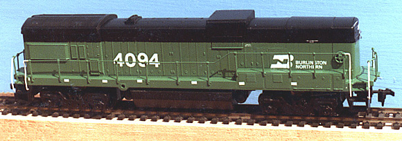
The B30-7A's are in the standard BN green and black paint scheme. The green band extends upward from the walkway six feet. The rest of the body and underframe are black, with the exception of the side sills, which are green. All handrails are green except for the vertical rails adjacent to each corner step which are white. The bottom step edges are trimmed in white as a safety feature. This two color paint scheme can be painted in either of two ways. The green can be painted first, followed by the black, or the black first, followed by the green. I had already installed the handrails so I painted the black areas first. When it was thoroughly dry, the walkways, pilots, top and upper sides were masked off. The remainder of the body, including the handrails, was sprayed with Floquil's BN green. After the green was dry to the touch, a smooth layer of Crystal Cote was sprayed on to provide a good surface for the decals. I used Microscale decals set No. 87-25, following their instructions for decal application, although I used Walthers Solvaset to set the decals. When everything was dry and completely set, a final finish was applied by spraying the entire model, including the chassis, with Testor's Dullcote. A very light weathering was created with Chalk-Ez powdered chalks, and Floquil's Dust was sprayed on very lightly.
The last two things I do on a locomotive model are to cement the class light jewels and install the couplers. Drill small counter-sunk holes for the four class light jewels and cement them in place with a miniature drop of CA cement or white glue. Kadee number 5 operating couplers were assembled in the draft gear boxes which were held with a little bit of liquid styrene cement. I drilled and tapped number 2-56 holes in the coupler mounting pads on the frame.The coupler boxes are attached with number 2-56 round head brass machine screws. Using a Kadee coupler gauge the couplers were checked for alignment and function with the chassis on a piece of straight and level track. This ensures good performance in operation, assuming the track is well laid and aligned. Burlington Northern B30-7A #4094 was put into service behind Athearn's BN GP50 #3114 and pointed west toward Seattle.
Athearn:
Detail Associates:
Details West:
Kadee:
Precision Scale:
Trackside Parts:
Utah Pacific:
Microscale:
Floquil:
Testors:
|
| Here are two B30-7A GIF files for those who enjoy creating GIF scenes using Microsoft's Explorer web browser. They were drawn by Erik Rasmussen: |
 |
 |
|
For those who wish to view prototype photographs of Burlington Northern's
B30-7A fleet, please visit Charles Biel's site: TrainPix.com - BN B30-7A Photograph Site
|
Page layout and Graphics are copyright © 2002 by QStation.org